

Crush power consumption of the "Always-On Domain" for battery lifetime
January 2016

Almost every device available on the market today has low-power requirements, regardless of whether it is a mobile application, while another trend, driven by consumers' wishes, demands to integrate more and more features. Hence, defining a variety of power management modes becomes essential for SoC architects with the challenge to find the appropriate balance between competing requirements.
Low-power design techniques have naturally evolved to meet this demand: power-gating now complements clock-gating and multi-voltage design is becoming common.
The specificity of mobile applications (such as Wearables) is to spend most of the time in an inactive mode. Thus, the active power becomes a secondary factor of the overall power equation and it is crucial to minimize the current drawn in low-power mode. Doing so requires determining what functions need to be kept active or retained, and what should be shut-off.
The domain of the circuit which is supplied throughout all SoC operating modes, including the lowest power mode, forms its "Always-On Domain". Interestingly, some functions in this domain still may be kept inactive.
Therefore, the questions become: what subset of the design needs to be maintained alive to be able to wake-up the system and how can the power budget of this domain be wisely minimized?
1. What is the purpose of the Always-On Domain and what does it include?
The Always-On Domain is the first part of the circuit supplied at power-up, in order to manage the boot sequence, and it remains powered, whatever the mode, until the whole system is completely shut-down.
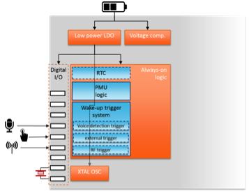
Since the Always-On Domain aims at providing a means to wake-up from "sleep" modes and resume normal operation, it includes a digital logic block ("always-on logic") that needs to be kept active to process the events used to trigger the wake-up of the whole device, along with the related infrastructure (power supply, clock, I/O...).
The "Always-on logic" may include wake-up triggers, be they external (light sensor, push button...) or internal (RTC, voice activity detection, voltage detector...), as well as a power management controller ("Activity Control Unit" or "Power Management Unit" logic) to turn on the functional blocks that have been powered down in sleep mode.
The contents of the Always-On Domain can vary significantly in function of the application. Indeed, each wake-up trigger has specific requirements: e.g. a Real-time Clock (RTC) needs a 32 kHz oscillator (XTAL or RC), a voice activity detection trigger requires a faster clock (few MHz) and some digital I/O pads to connect a microphone. Some triggers may also include an analog sensor.
The elements of the power supply network (LDO(s), voltage comparator to monitor battery voltage level...) are also part of the Always-On Domain, if they are embedded in the SoC.
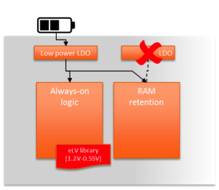
Depending on the type of data that need to be preserved in "sleep" modes, the Always-On Domain may also include an SRAM with retention mode, a power gated block with retention registers and/or a synthesizable register array placed in the always-on logic.
2. How to keep the power consumption of the Always-On Domain within the allocated budget?
It is now common, for battery-operated devices, to target power consumption lower than 1 uA in "sleep" mode. It can be pretty challenging to meet this power budget which imposes significant constraints on both operating frequency and voltage. Therefore, the required wake-up triggers must be consistent with these constraints: the triggering system must be kept small and with low frequency requirements.
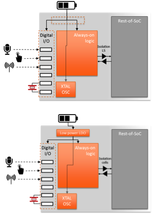
Regarding the power supply, designers have to choose between two schemes:
- A direct connection to the battery to avoid the need for any voltage regulator. All the functions included in the Always-On Domain have to rely on thick gate-oxide transistors to support an extended voltage range. Thick gate-oxide devices provide significantly lower leakage than standard devices, which gives an advantage to this scheme when the always-on logic operates at low frequencies (few tens of kHz).
- Low-voltage operation using an ultra-low power LDO (low drop-out) linear regulator. The power saving is immediate when operating at a lower voltage, but it comes with a severe impact on the maximum operating frequency. Therefore, it is required to select carefully the appropriate operating voltage, which can provide the optimal speed-versus-power compromise. Moreover, some elements of the Always-On Domain may not support ultra-low voltage operation (e.g. I/O or oscillator). As a result, the benefit of having two supply voltages in the Always-On Domain (low voltage and ultra-low voltage) depends on the comparison between the power saving coming from ultra-low voltage operation and the quiescent current of the regulator required to supply this voltage.
3. Solutions from Dolphin Integration to address these issues
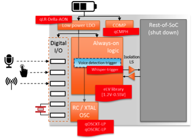
Dolphin Integration, building on 30 years of experience, provides a complete Silicon IP panoply to achieve low-power requirements for any Always-On Domain:
- Sesame BIV: Standard cell library (using a patented Flip-Flop) with extended operating range (up to 3.6V) using thick gate-oxide transistors
- Sesame eLV: Low voltage standard cell library operating down to the minimum data retention voltage
- QOSCXT-LP: Ultra-low power XTAL oscillator
- QOSCRC-LP: Ultra-low power RC oscillator
- qCMPH: Low-power voltage comparator
- WhisperTrigger™: Low-power Voice Activity Detection (VAD) trigger
- qLR Della AON: Ultra-low power cap-less LDO
AON diagram based on SESAME eLV library
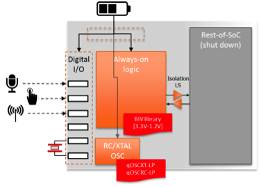
AON diagram based on SESAME BIV library
4. Complementary solutions to optimize a deep sleep mode
In order to further optimize a deep sleep mode, Dolphin Integration provides complementary solutions for efficiently implementing some low-power design techniques:
- An innovative and complete set of power management cells, called SESAME CLICK, which includes all the cells required for power gating techniques along with a patented Transition Ramp Cell (TRC) enabling a smart and safe management of in-rush current into the power island,
- SRAM with embedded power switches (ERS option), enabling easy control of low power modes (retention and shut-down)
- A dual regulator, called RAR, combining a high-efficiency switching regulator (eSR) with an ultra-low quiescent current linear regulator (qLR) optimized for the retention mode.
Last but not least, the SESAME eLV standard cell library has the capability to operate down to the minimum data-retention voltage. This new feature enables to share a voltage regulator between the Always-On Domain and a retention RAM for instance, thereby saving the area, the power and the BoM associated with a dedicated LDO for supplying the RAM.